Electrical Connection
Routing the Cables

First, the panel at the left side near the manometer should be removed to make the various electrical connections. A magnetic valve, water leakage sensor, automatic moisture meter, remote control and room
temperature sensor are supplied with the unit. Their cables can be led to the outside through the opening at the bottom of the panel. The power cable for the power supply can be led through the black feed-through rubber at the side of the unit.
ELECTRICAL CONNECTION
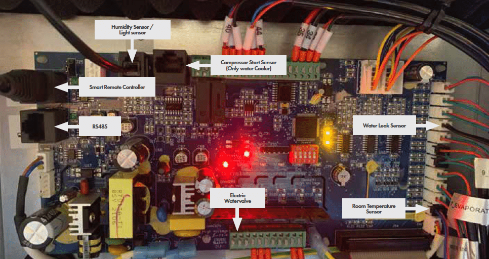
Automatic Humidity Sensor with light cell
The Automatic Humidity Sensor with light cell supplied with the unit can be found in the connection set supplied with Revomax. The cable should be led through the opening in the front panel and connected to the circuit board (see picture) The sensor should be hung in the room and may not be covered. The light cell determents if it’s night or day.
Room temperature sensor
The connection set also contains a room temperature sensor, which needs to be connected to the printed circuit-board. This sensor should be led to the outside through the opening in the panel and should be hung at the level of the upper side of the vegetation. The sensor should be protected against heat radiation and must be put in the shade. A protective cover over the sensor is sufficient.
The Smart Remote Controller
The smart remote controller can be found in a separate black box, the cable to connect the smart remote controller can be found in the connection set. The cable must be led through the opening in the panel and the UTP connector must be connected to the circuit board (see picture) The USB side of the cable can be plugged in one of the USB ports on the smart remote controller.
Power supply specifications
4 different OptiClimate models are available. For your safety and the safety of the OptiClimate, the following specifcations should be observed when connecting the power supply: use the circuit breakers (MCB) and cable thickness specifed. The cables for the supply voltage should be led through the grommet at the side of the unit and connected to the green screw terminal on the circuitboard as described in the illustration. The grounding can be connected to the PE at the bottom right of the metal back plate.

When it’s not possible to use a 3 phase power supply but only a single phase power supply is available the phase L1 + L2 + L3 need to be looped using a correct diameter wire. (only 6000 and 10000 models)